Introduction
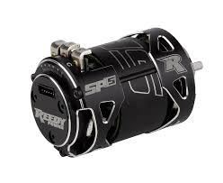
In modern motor control systems—especially in brushless DC (BLDC) motors used in robotics, RC vehicles, drones, and industrial drives—sensored motors (i.e. motors with position feedback sensors) require both power and low-level signal connections. The interface between motor and controller often includes solder tabs on the motor for power leads (A, B, C) and small wires for sensors (e.g. Hall sensors, encoder).
A “solder tab vertical extension” is an accessory or modification that raises those connection points upward, rather than lying flat or flush with the motor housing. When properly designed for sensored motors (i.e. preserving signal integrity), these extensions offer practical and performance advantages.
This guide walks you through the motivations, design principles, installation techniques, and maintenance best practices of sensored motor solder tab vertical extensions.
1. Why Vertical Extensions? The Motivations
Accessibility & Ease of Assembly
In many motor installations, space is tight and wiring is cramped. Solder tabs that lie flat against the motor case are hard to reach with a soldering iron or to route wires cleanly. Raising them vertically gives more clearance, easier access, and reduced chance of unintended damage to nearby components.
Mechanical Stress Relief
Flat tabs transmit vibration, bending, or torque loads directly into solder joints. Extensions can act as buffers or “levers” that isolate mechanical stress, reducing fatigue and joint failure over time.
Thermal & Electrical Benefits
Longer, vertically oriented tabs or posts can provide more metal mass and surface area, helping with heat dissipation from current‐carrying junctions. Also, by enabling better routing, wire bending stress is reduced, helping maintain low electrical resistance at the joints.
Signal Integrity for Sensors
Sensored motors require not only high current paths but also sensitive, low-current sensor wiring (e.g. Hall sensors). A well-designed extension will incorporate proper shielding, trace layout, and grounding so sensor signals remain clean and unaffected by electromagnetic interference (EMI) from the power conductors.
Modularity & Serviceability
If the motor is swapped, serviced, or modified, vertical extensions simplify disconnecting and reconnecting wires. They become consistent, modular “adapter blocks” between the motor and the external wiring harness.
2. Key Design Considerations
To ensure an extension works well (especially for sensored motors), attention must be paid to several design constraints:
Conductor Material & Surface Finish
Use high-conductivity metals (e.g. pure copper, copper alloys) for low resistance. Surface plating (gold, tin, or silver) helps resist oxidation and ensures better solderability.
Geometry & Cross-Section
The cross-sectional area (thickness × width) of the extension must be sufficient to carry peak motor currents without excessive resistive losses or heating (I²R losses). For heavy-duty use, thicker/gusseted posts are required.
Insulation & Isolation
Sensor wires must be electrically isolated from power conductors. Use insulating materials (PTFE, PEEK, nylon, or high-temperature plastics) and adequate spacing. For high-noise environments, consider internal shielding or twisted‐pair routing for sensor lines.
Layout & Trace Routing
Power and sensor lines should be routed to minimize coupling. Sensor lines should avoid running in parallel right next to high-current copper paths. If the extension is a small PCB-style adapter, traces for sensor wires should be separated, with ground shielding if needed.
Height & Profile
The extension must be tall enough to provide clearance but not so tall as to interfere with the mechanical assembly. Low-profile vertical extensions are particularly useful when height is constrained.
Mechanical Support & Strain Relief
Adding fillets, reinforcements, or bracing helps prevent flexing under vibration. Strain relief (e.g. clamps or soft loops) on connected wires prevents pulling force on solder joints.
Compatibility & Fitment
Spacing between motor tabs, hole positions, and alignment must match the motor’s layout. Some manufacturers provide motor-specific vertical extension designs tailored to particular geometries.
3. Installation Step by Step
Here is an effective procedure to install sensored motor solder tab vertical extensions correctly.
-
Preparation & Cleaning
-
Clean the original motor tabs and the mating faces of the extension with isopropyl alcohol or a fine abrasive (e.g. fine grit sandpaper) to remove oxides, solder paste residue, or contaminants.
-
Ensure all parts are dry and flat.
-
-
Mechanical Alignment & Fixturing
-
Align the extension firmly against the motor tabs. Use a jig, fixture, or clamp to hold everything in place without movement during soldering.
-
Ensure no gaps or misalignment that may stress the joints.
-
-
Flux Application
-
Use rosin or no-clean flux to promote solder wetting. Apply flux to both surfaces generously but without overflow onto sensor traces.
-
-
Soldering Temperature & Technique
-
Use a temperature-controlled soldering station. Typical soldering temperature should be enough to melt the alloy (~350–400 °C, depending on alloy), but avoid overheating the motor internals (magnets, sensors).
-
Solder the power (high-current) connections first, so they provide a heat sink for subsequent joins.
-
Then solder the sensor wires (Hall sensor, ground, etc.) carefully, minimizing dwell time on the delicate parts.
-
-
Inspection & Rework
-
Visually inspect the joints: full fillets, no cold soldering, no solder bridges.
-
Use a multimeter to verify low resistance continuity across power lines.
-
For sensor lines, verify continuity and absence of shorts.
-
-
Testing Before Integration
-
Slowly spin the motor (with minimal load) and verify that sensor signals (in the ESC or controller) are present and stable.
-
Monitor for abnormal heating or instability before closing the assembly.
-
-
Final Assembly & Strain Relief
-
Secure wires with clamps, zip ties, or flexible loops to avoid stress on solder joints.
-
Route cables to avoid crossing moving parts or high-vibration zones.
-
4. Troubleshooting & Maintenance
Even well-installed extensions may require periodic care. Here are common issues and fixes:
Increased Resistance or Voltage Drop
Over time, oxidation, micro-cracks, or loose joints can increase resistance. Measure resistance periodically; if it rises, reflow or disassemble and clean.
Sensor Signal Noise or Dropouts
If sensor signals become erratic under load, it often points to signal wiring issues. Use an oscilloscope to view the Hall sensor lines. Add shielding, better routing, or filtering as needed.
Mechanical Loosening
Vibration may loosen or fatigue joints. Inspect mechanically for cracks or movement. Reinforce joints or introduce mechanical stiffening structures when necessary.
Thermal Cycling Stress
Repeated heating and cooling cycles can cause solder joints to fatigue. Use compliant wiring or flexible loops to absorb expansion/contraction. In extreme cases, rework joints or improve thermal management.
Inspection Intervals
In harsh or high-vibration environments, inspect solder joints monthly. In milder settings, every 3–6 months may suffice. Maintain logs of resistance trends, which often predict failures before they occur.
5. Use Cases & Applications
Sensored motor solder tab vertical extensions are especially valuable in:
-
RC vehicles and drones: Where compact layouts and frequent motor changes demand easy access and reliable connections.
-
Robotic actuators: In robots where tight integration means minimal space and high demands on signal fidelity.
-
Industrial motion systems: Where downtime is costly; easier maintenance and better reliability matter.
-
Prototyping & R&D: When motors are swapped often, extensions speed reconfiguration.
-
High-current drives: Where power leads carry heavy currents and need robust, low-resistance connections.
Conclusion
Sensored motor solder tab vertical extensions are a potent tool in the motor system designer’s toolkit. When properly designed, installed, and maintained, they deliver improvements in accessibility, mechanical robustness, thermal behavior, and signal integrity—all without compromising performance.
If you’re working with sensored BLDC motors and have faced difficulty routing wiring or servicing connections, integrating a high-quality vertical extension may be one of your best investments. Focus on conductor sizing, insulation, mechanical support, and precise soldering, and you’ll get a durable, reliable interface between the motor and the rest of your electronics.


